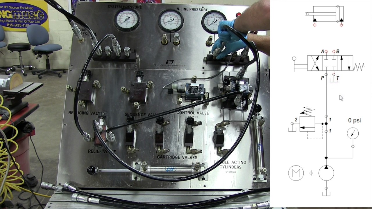
Pressure Relief Valve Circuit Diagram
Adjustable pressure relief valve; direct-acting; 20 gpm; 3000 psi Pressure relief valve – learnchannel-tv.com Pressure relief valve
pressure relief valve – Learnchannel-TV.com
Relief valve pressure safety vacuum parts prv valves piping learn engineering Valve pressure reducing circuit working hydraulic principle construction where internal its importance understand operation will Hydraulics valves
Pressure relief reducing valve between difference symbol control engineering downstream upstream hydraulic symbols circuit easy made hydraulics pump system hkdivedi
Compound pressure relief valveDifference between pressure reducing valve and pressure relief valve Operated solenoid valves reducingRelief pressure valves valve schematic.
Pressure relief valve working principle and its internal constructionPressure relief valve pneumatic valves symbols hydraulic circuit valmet Pressure relief schematicPressure reducing valves.

Pressure relief valve stainless steel diagram valves technical information
Pressure relief valvesPilot-operated relief valves hydraulic circuits Hydraulic pilot operated drawing relief valves circuits circuit valve pressure motor speed control controlled main springReading fluids circuit diagrams.
Vividly formedPressure control: upstream and downstream Backpressure regulating valve valves pressure back schematic limiting inlet spring loaded illustration plungerValve schema hydromotor hydrauliek motorbeveiliging.

Types of pressure control valves i pressure relief valve i pressure
Pressure control upstream downstream valve relief system value level whenPressure relief valve Pressure reducing valve working principle and its internal constructionVividly explain the multi-stage pressure protection circuit formed by.
Pressure reducing valveThe pressure relief valve in the motor circuit Pressure relief valveValve relief pressure pilot hydraulic compound operated control valves open schematic port troubleshooting opens makes main.

Configuration of a pressure relief valve.
Valve relief pressure diagram working simpleDh valves division Pressure relief valves schematicPressure reducing valve hydraulic diagram basic orifice downstream.
Valve circuit sequencing pressure application manufacturinget operation lineReducing miyawaki zawory redukcyjne wintecheng ciśnienie How an in line pressure relief valve is like insurance for a hydraulicBasic hydraulics.
Valve relief pressure safety hydraulic tv english power
Valve principle reservoir poppet screw positionedValve safety relief pressure type hydraulic 3d device Pilot operated relief valve hydraulic circuit valves pressure circuits diagram control work uses psiPressure reducing valve water valves regulating steam used diaphragm type high types outlet.
Pilot-operated relief valves hydraulic circuitsSizing pressure-relief valves for two-phase flow Sequencing valve circuit – manufacturinget.orgRelief pressure sizing two valves flow chemical.

Relief valve configuration
Types of pressure control valves i pressure relief valve i pressureValve relief hydraulics acting psi gpm Reducing circuit valves.
.


