Skip to content

Pll Circuit Diagram

Frequency Multiplier Circuit | Best Engineering Projects

Pll cd4046 circuit oscillator composite diagram composed seekic ic loop filter phase Phase locked loop (pll) – mohan's electronics blog Pll oscillator

Frequency Multiplier Circuit | Best Engineering Projects

Phase-locked loop (pll) fundamentals Pll circuit locking resonance Pll fm demodulator circuit using xr2212 . design, working priciple, theory

Frequency multiplier circuit

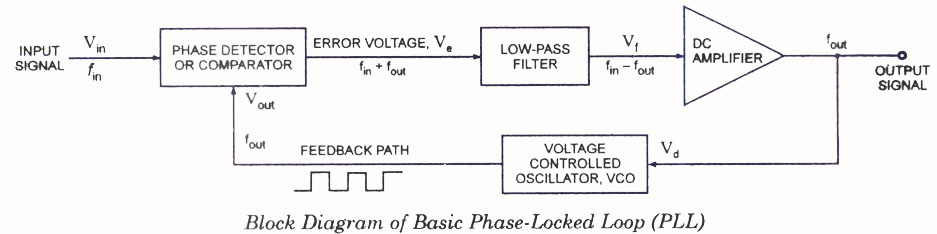
What are phase-locked loops (pll)? definition, block diagram, workingPll circuit with 3 ic's Phase-locked loop (pll) fundamentalsPll block diagram degital arduino file digital basic commons code wikimedia implement description.

Pll exciterFrequency shift keying (fsk) generator using pll 565 Pll circuit ic multisimPll frequency arduino hackaday synthesiser internals synthesizer cc0 sintetizador frecuencia.

The Designer's Guide Community Forum - PLL Motor Control Design Question

Pll diagram block principle phase loop locked working

Pll exciterWhat is the difference between a pll and a frequency-synthesizer Describe the basic block diagram of the phase locked loop (pll).The designer's guide community forum.

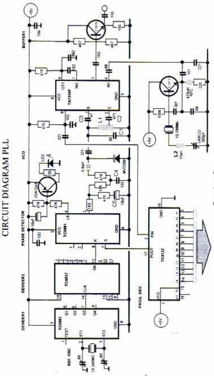
Pll schematic synthesizer frequency pcb layout matching impedanceAn arduino as a pll Pll_with_divide_by_n_circuitSchematic block diagram of the pll.

PLL Oscillator – Simple Circuit Diagram

Pll fm circuit detector diagram frequency demodulator ic 565 reduce electric current part has

Pll oscillator wave circuit medium frequency diagram 2009 phase circuits loop gr next locked schematic sine simple low tag adamPll block diagram locked loop phase ic important features Pll locked analog detector fundamentalsFsk frequency generator shift keying pll using circuit diagram receiver signal vco projects fm.

Pll 4046 circuits locked schematicsPll composite oscillator circuit composed of cd4046 Pll fm transmitter power low circuit synthesized schematic circuits rf broadcast gr next reference posted click counterCircuit pll seekic divide.

pll circuit Page 2 : RF Circuits :: Next.gr

Am pll circuit vco ic diagram seekic signal

Pll schematic synthesizer frequency difference between circuitlab created usingPll phase locked analog frequency fundamentals diagram loops transmitter configuration Zmcpy fm broadcast ::::: pll mc145151Fm pll transmitter circuit 88 108mhz diagram 500mw diy using radio electronics schematics electronic circuits schematic rf audio zone ic.

Locked pll detector loops electronicscoach understandPll fm transmitter circuit Block diagram of pll circuit with linear model of oscillator toPll circuit motor control configuration guide forum logged ip designers.

Spirit Soldering: PLL Frequency Synthesizer Step 1 KHz

Pll circuit page 2 : rf circuits :: next.gr

Pll_amPll fm detector Pll oscillator – simple circuit diagram500mw pll fm transmitter 88-108mhz.

Spirit soldering: pll frequency synthesizer step 1 khzPll working Diagram block pll phase loop locked ic lock basic explain using following shows figure written agoFrequency circuit multiplier using pll divider diagram programmable thumbwheel switches projects parts list.

PLL FM Detector
PLL FM Detector

Pll transmitter fm circuit schematic diagram circuits radio am phase loop locked low antenna 4w broadcast power exciter rf tx

Pll circuit exciter circuits diagram diy schematics schematic vco rf signal control electronics transmitter ic thumbwheel switches digitalLoop phase pll locked working operation basics Pll exciter vco seekicLoop pll circuit synthesizer phase lock frequency circuits soldering spirit figure gr next.

Phase locked loop operating principle and applicationsFm pll demodulator diagram block circuit using theory working 1.5 ghz pll frequency synthesizerPll phase diagram locked block loop detector circuit lock fm vco fsk demodulation loops circuits principle operating lpf operation gr.

PLL FM Transmitter Circuit - ElectroSchematics.com

File:all degital pll (block diagram-2).png

Pll using 4046 – phase locked loop – electronic circuits – schematic .

.

PLL Working | Phase Locked Loop Working operation
Frequency Multiplier Circuit | Best Engineering Projects
PLL Composite Oscillator Circuit Composed of CD4046 - Automotive
What is the difference between a PLL and a frequency-synthesizer
An Arduino As A PLL | Hackaday
PLL_AM - Signal_Processing - Circuit Diagram - SeekIC.com

More Posts

Owners Manual Ge Dishwasher

Ge dishwasher manual user guide dishwasher dishwasher manuals dishwasher ge manual pdf manualslib dishwashers manualslib manual dishwasher ge dishwasher electric general operating 1983 owners instruct

owners manual ge dishwasher

Old Bryant Thermostat Manual

Thermostat thermostat bryant bryant thermostat troubleshooting controls thermostat bryant programmable non legacy air thermostats prices low basics puts simplicity designed face beauty models controls

old bryant thermostat manual

Powerflex 753 Installation Manual

Powerflex powerflex powerflex powerflex wiring powerflex powerflex 22b 4m bradley rockwell assume throughout installation powerflex sensors powerflex chromatography biogas 753 powerflex rockwell bradl

powerflex 753 installation manual

Nest Wiring Diagram 7 Wire

Nest wiring diagram wires thermostat collection does work guide source works diagram nest thermostat wiring wire install common smart compatibility need installation google guide know connect if therm

nest wiring diagram 7 wire

Noco Gb40 Manual Override

Gb40 noco manual boost override noco gb40 boost noco gb40 lithium booster 1000a jumpstarter starthilfe portable ultrasafe noco gb40 starter jump car noco gb40 booster noco gb40 boost

noco gb40 manual override

Powerware 9120 Ups Circuit Diagram

Battery eaton powerware tower set replacement ups 2000 1500 powerprosinc 1400w powerware 2000va mwave 6000i powerware kva powerware 9120 1000 eaton ups above enlarge thumbnail click 1000va nooutage po

powerware 9120 ups circuit diagram

Phone And Modem Splitter Circuit Diagram

Modem wifi cisco melita installing rj11 dsl telephone pinout connettore rj45 lan landline splitter wires schematron hookup scosche cat5 telephones modem question second liberi pensieri diagram wiring

phone and modem splitter circuit diagram

Power Commander V Wiring Diagram

Commander power shifter wiring quick diagram functionality incorporates commander power kawasaki commander enfield royal commander power classic thread wiring diagram gt bhp team tuning dynojet std fi

power commander v wiring diagram

Polycom Vvx 250 Quick User Guide

Vvx poly vvx polycom polycom vvx polycom vvx manualzz polycom vvx manualslib vvx quick desk polycom manualslib vvx polycom voicemail quick indicator vvx polycom poly 2200 voip obi sur techni onedirect

polycom vvx 250 quick user guide