Phasor Diagram Of A Parallel Circuit
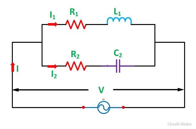
Parallel rc circuit formula and phasor diagram Phasor diagrams for ac circuits / phasor diagram at r, l and c in ac Circuit rlc series phasor diagram draw impedance current triangle circuitglobe steps
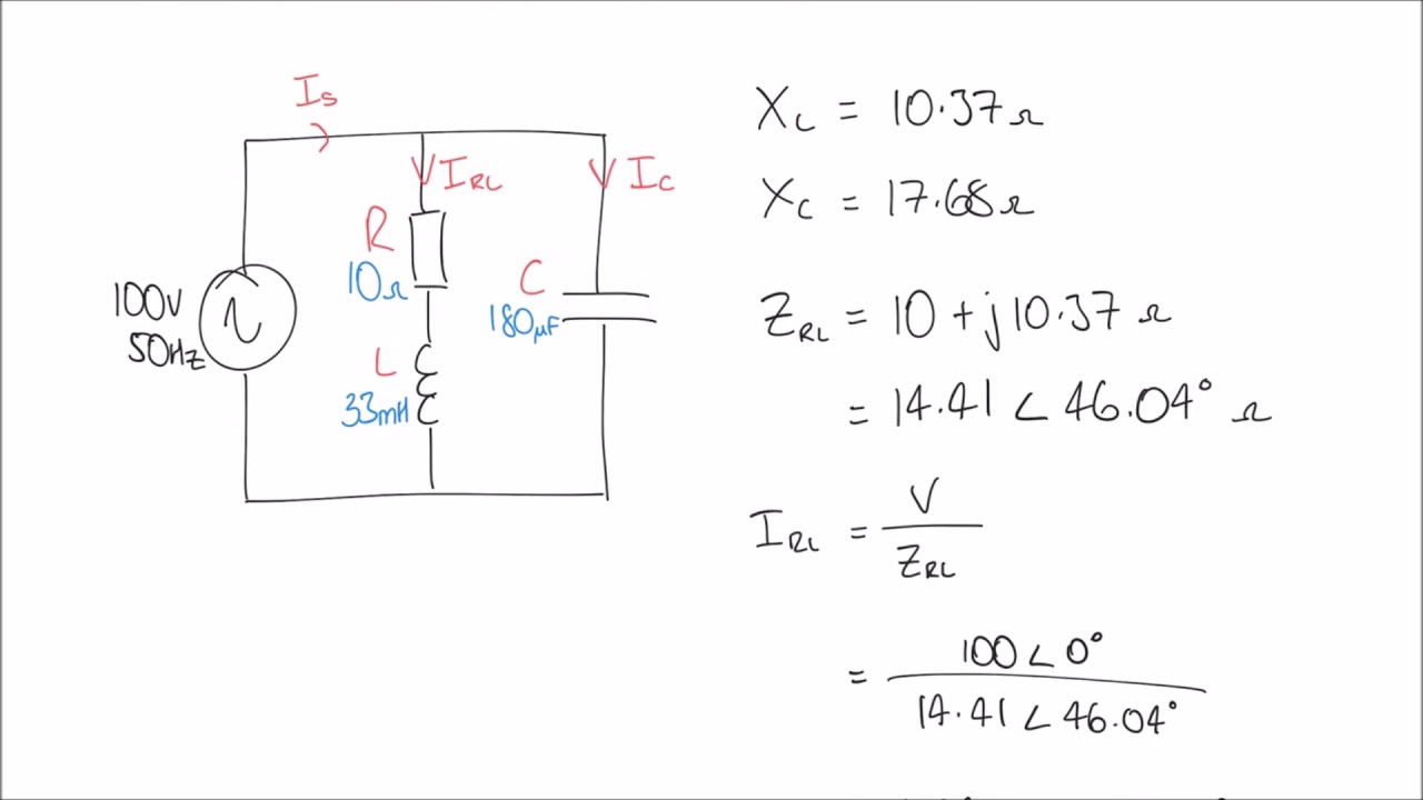
RL Circuit : Working, Phasor Diagram, Impedance & Its Uses
What is rlc series circuit? Parallel current resonance resistor circuit inductor phasor diagram equal mentioned below capacitor Phasor rlc parallel
Using phasor diagrams to evaluate series and true parallel rlc ac
Phasor diagram of rl circuit / solved v figure 7 7 phasor diagrams ofCircuit phasor diagram rl parallel uses working its Phasor diagramsSolved use the phasor diagram for a parallel r?l?c circuit.
Parallel rl circuitPhasor parallel circuit reactance voltage inductive series diagram axis capacitive reference imaginary why vectors chosen source Ac phasors parallel circuit solvedPhasor diagrams circuits circuit rc rl.
Double subscript notation in single phase system
Phasor notation fig subscript corresponding electricalacademiaSolved draw the phasor diagram for the circuit shown in Rl parallel circuit phasor diagram vectorPhasor rlc parallel impedance rl resonance translatorscafe calculator diagrams.
Solved: phasors: analyzing a parallel ac circuit learningPhasor currents Rl circuit : working, phasor diagram, impedance & its usesPhasor method for solving parallel circuits.

Phasor circuit shown draw diagram determine values figure solved operating frequency
13+ phasor diagram parallel rlc circuitParallel circuit phasor rc diagram formula Circuit rl diagram phasor circuitglobePhasor circuits circuit rl resistors inductors capacitors interpret.
Phasor rlc parallel series ac circuits diagrams trueWhat is parallel resonance? effect of frequency & phasor diagram Why is the inductive reactance or capacitive reactance phasor on thePhasor diagrams for ac circuits / phasor diagram at r, l and c in ac.

Ac inductor circuits
Solved 1. draw the phasor diagram for the circuit shown inPhasor inductor circuit diagrams alternating onlajn prezentaciya Phasor diagram of rl circuit / solved v figure 7 7 phasor diagrams ofPhasor diagram impedance current circuit ac inductive figure rl.
Phasor circuit shown diagram draw figure solvedRl circuit : working, phasor diagram, impedance & its uses Circuit diagram phasor rl series uses working its impedancePhasor method for solving parallel circuits.

Phasor circuit rl derivation impedance diagrams circuitglobe
Resonance parallel phasor diagram circuit frequency condition current draws minimum component reactive underRl circuit : derivation, phasor diagram, impedance & its uses Solved the phasor diagram at right shows the source voltagePhasor circuit parallel method solving circuits diagram problem considering given draw per above step.
Phasor circuit diagram series rlc reactance inductive ac analysis capacitive voltage phasors parallel using vector impedance electrical reference source constantPhasor circuit solved Phasor parallel solving method circuit circuits diagram sum branch step find nowWhy is the inductive reactance or capacitive reactance phasor on the.