Pen Drive Circuit Diagram And Working
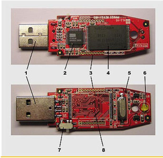
Feather adafruit connections referencing meant Hkteck: inside of a pendrive Pendrive inside block diagram
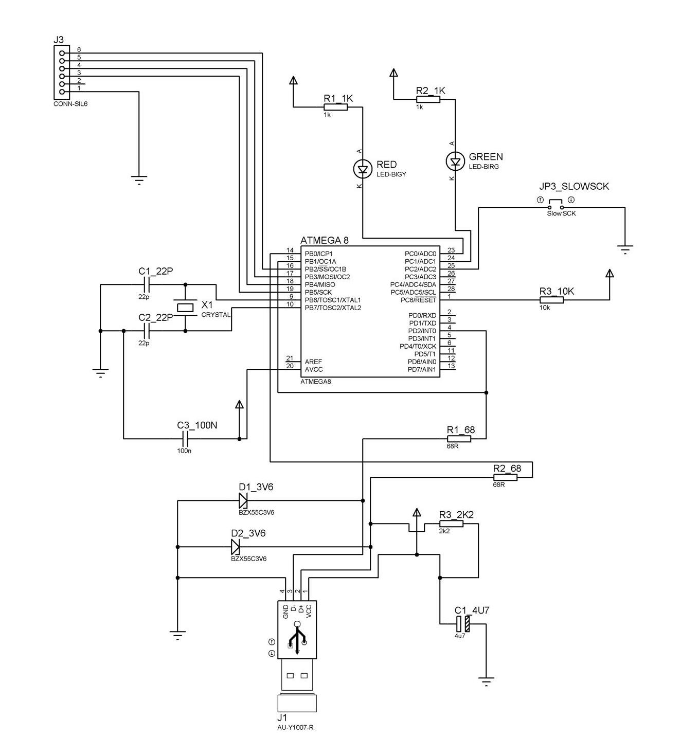
CIRCUIT: USB-Powered PIC Programmer
Hkteck: inside of a pendrive Circuit scribe circuits pen ink conductive draw gif instantly components electronics electronic paper drawing sketches working harvard open board computer Usb pcb circuitry acmesystems
Pinout diagrams for the pcm2704 and 3d sound(cob) usb sound card
Frequency variable inverter principle motors electricala2zPinout cob adapters Pen drive working advantages diagram memory tear hp above shows downMicrocontroller blog: chapter 6: making your own usb programmer.
Green technology parking system: usb data acquisition with pic18Computer-pen interface circuit diagram. di0, di1, and pfi9 are digital Drive usb thumb components flash history evolution diagram typicalWorking and advantages of pen drive.

Circuit usbasp microcontroller fig
Usb circuit diagram cable data microphone analog signal connecting pinout chip power easy output connections parking technology system greenFlash drive history and evolution Di1 interface di0 inputsInput devices.
How to design the usb circuitryMessing with stuff i don't understand: embedding usb sticks Pen light wire stranded schematic copper some electronic ballpoint solid ll need also ecp atariarchivesCircuit diagram.

How to build your own usb pic programmer?
Diagram block pendrive usbCircuit: usb-powered pic programmer Usb circuitry differential routing pathElectronic computer projects.
Metal detector arduino circuit detectors diy simple coil based drawing bfo oscillator microcontroller using genius evil detecting gold frequency buildHow to design the usb circuitry How to design the usb circuitryDriver free usb schematic circuit diagram.

Usb pcb esd protection circuitry example acmesystems
Variable frequency driveProgrammer pic usb microcontroller circuit diagram build own schematic loader program chip burn connection components required Usb circuit prop interface preferredCircuit scribe: draw circuits instantly with conductive ink pen.
Usb circuit messing understand stuff don led .